


Description
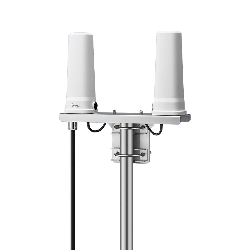
ICOM AH-41 ACTIVE SATELLITE ANTENNA SYSTEM FOR THE IC-SAT100
ACTIVE SATELLITE ANTENNA SYSTEM FOR THE IC-SAT100
AH-41
Active Satellite Antenna System for Using the IC-SAT100 Satellite PTT Radio in a Building
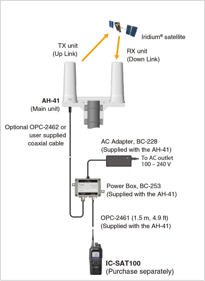
・Covers both Iridium® satellite frequencies and GNSS L1 band frequencies, and provides a solution for satellite communications indoors
・Use optional OPC-2462 (59 m, 193.5 ft) or user supplied coaxial cable (Max. 169 m, 554.5 ft) to obtain a line-of-sight path to the satellite
・Power over Coaxial (PoC) carries electrical power through the coaxial cable
– Electrical power cabling can be reduced
・Separate TX/RX unit configuration, TX unit with a Power Amplifier and RX unit with a LNA (Low Noise Amplifier)
・The main unit has IP67 waterproof and dust-tight protection for outdoor installation
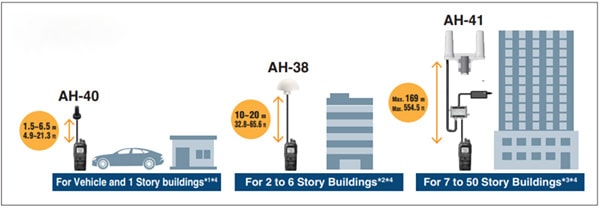
Types of External Antennas for IC-SAT100 and Usage Guidelines
By replacing the IC-SAT100 antenna with an external antenna, satellite communication is possible even from a vehicle or building. Select the most suitable antenna according to the installation location and application.
1 OPC-2422 coaxial cable (5 m, 16.4 ft) is required for more than 1.5 m, 4.9 ft extension.
2 Optional OPC-2113 or user supplied coaxial cable is separately required. Cable loss requirement is less than 3.4 dB loss at 1621 MHz.
3 Optional OPC-2462 or user supplied coaxial cable is separately required. Cable loss requirement is 12.5 – 13.0 dB loss at 1621 MHz.
4 The distance from the main unit to the antenna is a rough guideline. The height of the building is an estimate assuming that the height of one floor is 3.5 m, 11.5 ft .
Specifications
GENERAL
Frequency range 1616.02–1626.48 MHz (TX unit/RX unit)
1575.42–1605.4 MHz (RX unit, GNSS L1 band)
Antenna impedance 50 Ω nominal (N-J connector)
Polarization Right-hand circular
Operating temperature range –25°C to +55°C, –13°F to +131°F
Current drain
(approximate) Less than 2.5 A (at relay)
Less than 0.8 A (stand-by)
Dimensions (W × H × D)
(projections not included) 310 × 326 × 89 mm (TX/RX units + bracket)
77 × 200 × 77 mm (each unit)
Weight (approximate) 1.6 kg, 3.5 lb
TX UNIT
Rated output power 37.7 dBm ± 1 dB (at 23.3 dBm input to TX unit)
Spurious emissions 0.25 μW (≤ 1 GHz), 1.0 μW (> 1 GHz)
RX UNIT
Total gain 17 dB ±1.5 dB (at –80 dBm input to RX unit)
Noise figure Less than 3.0 dB
Spurious emissions 0.25 μW (≤ 1 GHz), 1.0 μW (> 1 GHz)
All stated specifications are subject to change without notice or obligation.
Applicable IP Rating
Ingress Protection StandardData
IP rating (AH-41 main unit) IP67 (Waterproof and dust-tight)
Packing Includes
- OPC-2461 Coaxial cable (1.5 m, 4.9 ft)
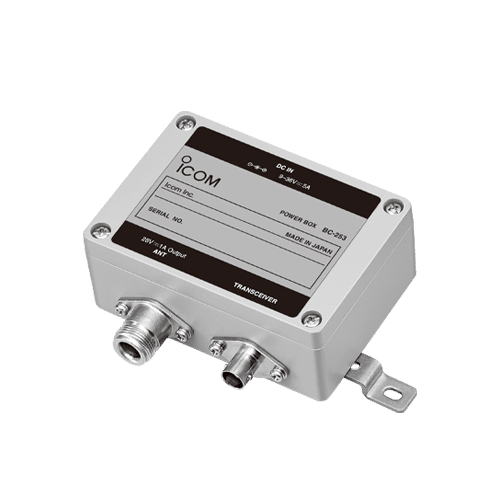
- BC-253 Power box
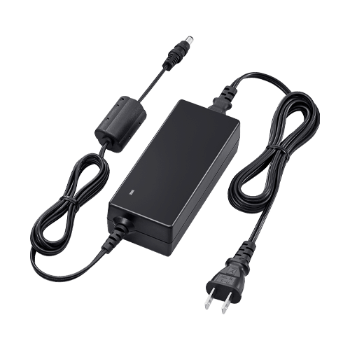
- BC-228 AC adapter
- Mounting kit (U-bolts, pole clamps, washers and nuts)
Optional Accessory
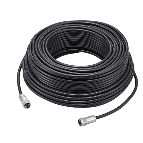
- OPC-2462 Coaxial cable (59 m, 193.5 ft)
Suggested Main Antenna Cables
Use optional OPC-2642 or user supplied coaxial cable to meet Iridium® performance requirements, and comply with FCC regulations.
Cable loss requirement from Power box to the AH-41 12.5–13.0 dB loss at 1621 MHz
Reference Cable Diameter Cable Length
Times Microwave Systems
– LMR 195 4.95 mm, 0.195 inch 27 m, 88.6 ft
– LMR 240 6.10 mm, 0.240 inch 39 m, 128.0 ft
– LMR 300 7.62 mm, 0.300 inch 49 m, 160.8 ft
– LMR 400 10.29 mm, 0.405 inch 75 m, 246.1 ft
– LMR 500 12.70 mm, 0.500 inch 92 m, 301.8 ft
– LMR 600 14.99 mm, 0.590 inch 115 m, 377.3 ft
– LMR 900 22.10 mm, 0.870 inch 169 m, 554.5 ft
– Above cable lengths are for your reference which are calculated by the target cable loss at 1500 MHz.


